Home » Without Label » 555 Timer Schematic : Simple Timer Alarm Circuit using IC 555 / The second 555 timer helper will extend the timers output duration without having to use large values of r1 and/or c1.
555 Timer Schematic : Simple Timer Alarm Circuit using IC 555 / The second 555 timer helper will extend the timers output duration without having to use large values of r1 and/or c1.
555 Timer Schematic : Simple Timer Alarm Circuit using IC 555 / The second 555 timer helper will extend the timers output duration without having to use large values of r1 and/or c1.. To understand the basic concept of the timer let' s first examine the timer in block form as in figure 1. Its name is derived from three 5k ohm resistors ,connected in series used in it.the timer ic can produce required waveform accurately. Figure 2 shows the basic 555 timer monostable circuit. The standard 555 timer ic is made of 2 diodes. Simple 555 timer circuits & projects.
In 2017, it was said over a billion 555 timers are produced. A monostable 555 timer is required to produce a time delay within a circuit. Simple 555 timer circuits & projects. The standard 555 timer ic is made of 2 diodes. We have a large collection of simple and advanced projects using 555 timer ic.
555 Timer Basics - Astable Mode from www.circuitbasics.com The time intervals can be used for keeping a relay controlled load on or activated for the desired amount of time and an automatic switch off once the delay period. These on off intervals can be adjusted by varying the 555 timer output and number of counter outputs. Figure 2 shows the basic 555 timer monostable circuit. The working modes of a 555 timer are astable, bistable, and monostable. If a 10uf timing capacitor is used, calculate the value of the resistor required to produce a minimum output time delay of 500ms. The general 555 timer circuit schematic at the heart of the circuit is a lm555 ic, which includes 23 transistors, 2 diodes and 16 resistors on a silicon. The 555 timer is a simple integrated circuit that can be used to make many different electronic circuits. This tutorial provides sample circuits to set up a 555 timer in monostable, astable, and bistable modes as well as an in depth discussion of how the 555 timer works and how to choose components to use with it.
We connect a 100μf capacitor to the positive voltage supply and then to pin 2.
Working modes of 555 timer ic. In this video we look at a simple 555 astable circuit. The ratio of these times can be varied by changing r1, r2 and c1 in a typical 555 astable arrangement or r1, vr1 and a change of capacitor via the jumper (c1) within this pwm circuit. Its name is derived from three 5k ohm resistors ,connected in series used in it.the timer ic can produce required waveform accurately. Simple 555 timer circuits & projects. The ratio of these times can be varied by changing r1, r2 and c1 in a typical 555 astable arrangement or r1. Referring to the timing diagram in figure 3, a low voltage pulse applied to the trigger input (pin 2) causes the output voltage at pin 3 to go from low to high. The timer's internal circuitry is largely responsible for this triggering but it is also caused stray or installed capacitance at the trigger input of the timer. Circuits into the ever increasing ranks of timer users. To understand the basic concept of the timer let' s first examine the timer in block form as in figure 1. 500ms is the same as saying 0.5s so by rearranging the formula above, we get the calculated value for the resistor, r as: We have a large collection of simple and advanced projects using 555 timer ic. The 555 timer ic is an integrated circuit (chip) used in a variety of timer, delay, pulse generation, and oscillator applications.
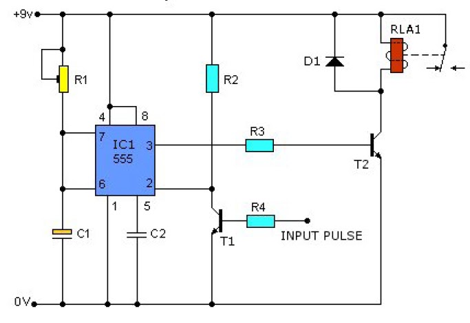
Figure 2 shows the basic 555 timer monostable circuit. Let us discuss in detail about this circuit. Daman shah june 5, 2021. 555 timer helpers schematic the addition of a capacitor to the trigger will not work for short output pulses as there is also a short delay in the recovery of the trigger terminal voltage. A monostable 555 timer is required to produce a time delay within a circuit.
gadgets projects electronics - Simple Electronic Projects from 1.bp.blogspot.com The circuits explained here are 10 best small timer circuits using the versatile chip ic 555, which generates predetermined time intervals in response to momentary input triggers. The time intervals can be used for keeping a relay controlled load on or activated for the desired amount of time and an automatic switch off once the delay period. Here, with the help of the 555 timer ic, we are eliminating the need of manually switching on or off the device. These on off intervals can be adjusted by varying the 555 timer output and number of counter outputs. As discussed in the above section, the ic is in its standard monostable mode. Referring to the timing diagram in figure 3, a low voltage pulse applied to the trigger input (pin 2) causes the output voltage at pin 3 to go from low to high. The timer's internal circuitry is largely responsible for this triggering but it is also caused stray or installed capacitance at the trigger input of the timer. 555 ic timer block diagram 555 ic timer block diagram.
In 2017, it was said over a billion 555 timers are produced.
Basic 555 monostable multivibrator circuit. Simple 555 timer circuits & projects. 555 timer circuits (133) browse through a total of 133 555 timer circuits and projects including the timer's datasheet. The breadboard schematic of the above circuit is shown below. To understand the basic concept of the timer let' s first examine the timer in block form as in figure 1. The 555 timer can be used with a supply voltage (vs) in the range 4.5v to 15v (18v is. The ratio of these times can be varied by changing r1, r2 and c1 in a typical 555 astable arrangement or r1. We connect a 100μf capacitor to the positive voltage supply and then to pin 2. The standard 555 timer ic is made of 2 diodes. 555 timer circuits (133) browse through a total of 133 555 timer circuits and projects including the timer's datasheet. Also, 555 timer is used to generate an oscillating pulse. This tutorial provides sample circuits to set up a 555 timer in monostable, astable, and bistable modes as well as an in depth discussion of how the 555 timer works and how to choose components to use with it. Resistive network consists of three equal resistors and acts as a voltage divider.
Because of their availability and ease of use, the 555 astable circuit is the common source of clock signal in many synchronous circuits. To understand the basic concept of the timer let' s first examine the timer in block form as in figure 1. 555 timer is an industrial standard ic existing from early days of ic. The output voltage from the chip is around 1.5 v lower than vcc when high and around 0 v when low. In this mode, the circuit of the ic 555 timer produces the continuous pulses with exact frequency primarily based on the value of the two resistors and.
The Three Fives Kit: A Discrete 555 Timer - RF Cafe from www.rfcafe.com The circuits explained here are 10 best small timer circuits using the versatile chip ic 555, which generates predetermined time intervals in response to momentary input triggers. Lm555 timer 1 features 3 description the lm555 is a highly stable device for generating 1• direct replacement for se555/ne555 accurate time delays or oscillation. This tutorial provides sample circuits to set up a 555 timer in monostable, astable, and bistable modes as well as an in depth discussion of how the 555 timer works and how to choose components to use with it. Resistive network consists of three equal resistors and acts as a voltage divider. Daman shah june 5, 2021. We have a large collection of simple and advanced projects using 555 timer ic. Adjustable on off timer(using 555 astable mode) in this circuit a timer with cyclic on off operations is designed. Using the 555 timer ic in special or unusual circuits.
The 555 is also very versatile, and can be used.
The ratio of these times can be varied by changing r1, r2 and c1 in a typical 555 astable arrangement or r1. Because of their availability and ease of use, the 555 astable circuit is the common source of clock signal in many synchronous circuits. Once this switch is pushed, the circuit pulls its output to a. In 2017, it was said over a billion 555 timers are produced. The ratio of these times can be varied by changing r1, r2 and c1 in a typical 555 astable arrangement or r1, vr1 and a change of capacitor via the jumper (c1) within this pwm circuit. In this project, we are using 555 timer ic to create various timer circuit like 1 min timer circuit, 5 min timer circuit, 10 min timer circuit, and 15 min timer circuit. To understand the basic concept of the timer let' s first examine the timer in block form as in figure 1. Referring to the timing diagram in figure 3, a low voltage pulse applied to the trigger input (pin 2) causes the output voltage at pin 3 to go from low to high. The timer's internal circuitry is largely responsible for this triggering but it is also caused stray or installed capacitance at the trigger input of the timer. The 555 timer is a chip that can be us… We connect a 100μf capacitor to the positive voltage supply and then to pin 2. Lm555 timer 1 features 3 description the lm555 is a highly stable device for generating 1• direct replacement for se555/ne555 accurate time delays or oscillation. These on off intervals can be adjusted by varying the 555 timer output and number of counter outputs.